
Rotary Engines | Auto Mechanics 101

We owe the creation of the rotary engine to a certain Dr. Felix Wankel. In 1924, at the age of 22, he created his research laboratory dedicated to the design of a rotary engine. Interested in his work, the German Ministry of Aviation subsidizes its research during the Second World War, believing that it would be the future of engineering. After the war, a motorcycle manufacturer, NSU, creates a partnership with Wankel.
In 1958 was born the first functional and practical rotary engine, the KKM. With a single rotor, the KKM has a total displacement of 400 cm³. NSU officially announces, in 1959, the success of the Wankel rotary engine. More than one hundred companies around the world at this time take ownership of the technical plans of this engine. Thirty-four of them are Japanese.
Several manufacturers tried to develop this concept without coming up with a finished product. Strangely, only a small Japanese company named Toyo Kogyo continues the research, while others give up. Jujiro Matsuda, then president of the company, is convinced of the potential of this revolutionary engine. In 1961, he signed a contract with NSU to jointly design a viable prototype. Following the success of its most successful division, Toyo Kogyo is renamed in the name of the famous manufacturer that everyone knows today as Mazda.
Reliability problems
In 1963, Mazda opens its research division dedicated solely to the rotary engine. Kenichi Yamamoto, who is then head of this division, has more than 47 engineers at his service. His mission? Find a practical use of the rotary engine to target mass production and commercial sale. Two major problems delay its marketing: premature wear of internal components and extremely high oil consumption. After many months of research and more than 300 hours of testing, new seals and oil designed specifically for the rotary engine address these two major problems.
Unlike the original concept, Mazda prefers to design a multirotor engine. The single-rotor prototype built by NSU was, at low speeds, rather anemic in torque and suffered from instability that resulted in unpleasant vibrations. In December 1964, the research division produced a double-rotor engine with a 491cc combustion chamber, called the type 3820. This engine quickly made its way to the production lines under the code name 10A.
The official launch

The 10A is the first rotary engine to be marketed in a car. Its first appearance dates back to May 30, 1967, when Mazda sells the Cosmo Sport, the only single-rotor racing car in the world. Equipped with a dual four-barrel carburetor mounted laterally on the intake ports and spark plugs for each rotor, the 10A develops a 110hp power output. Considering the lightness of the car and the technology available at the time, the Cosmo Sport is considered a technological feat by the automotive press.
It wasn’t until 1970 that Mazda began exporting its vehicles to North America. Unfortunately, the United States is, at the time, in the process of adopting strictest emission standards. Moreover, they are in the midst of an oil crisis. To counter the problem, Mazda creates a thermal reactor that burns polluting emissions. The manufacturer can finally market the first rotary engine car in North America, the R100.
Other innovations, such as high-intensity ignition systems and reactive exhaust manifolds, enable Mazda to reduce fuel consumption by up to 40%, ensuring the viability of the North American rotary engine.
Continuous improvement
As a result of its success in reducing pollutant emissions and fuel consumption, Mazda is pushing its research to maximize the performance of its rotary engines. One of the first improvements made was the design of a six-port intake for the 12A rotary engine (two 573 cc chambers). Each rotor is equipped with three intake ports whose opening is controlled in two stages. This mechanism improves fuel efficiency without sacrificing high-end performance. One of the first cars – and certainly one of the best known – to benefit from this engine is the very first version of the RX-7, the FB3S, born in March 1982. However, it will be necessary to wait until 1983 before seeing the first turbocharged RX-7.
Turbocharging and rotary engines have always worked well. This is mainly because rotary engines tend to release greater energy from the exhaust port when compared to traditional engines. This character trait can be attributed to the sudden opening of the exhaust ports which are in direct line with the rotor expulsion motion. And, of course, more energy coming out of the exhaust allows better use of a turbocharger.

Compact sport classics
The second generation of the RX-7, the FC3S, is probably better known to rotary engines neophytes. Four versions are available at the time, namely the SE, GTU, GLX, and Turbo II. The first three are powered by an atmospheric version and have the electronic injection of the 13B engine (two chambers of 672 cc). Introduced in 1985 as 1986 MY, the FC3S is the first RX-7 to have disc brakes on all four wheels. The basic SE model is equipped with 14-inch wheels and two-piston front calipers. The GTU, considered as the sports version of the group, has an aluminum hood as well as four-piston calipers and the transmission of the Turbo II version. The GLX is equipped with the electric group and 15-inch wheels. Finally, the Turbo II version is the most powerful with its 13B-T mechanics. Mazda claimed that the turbo version of the 13B was developing 180hp at the crank.
In 1988, the FC3S is entitled to some aesthetic retouching and has a good kick in the backside performance-wise. The 13B’s cavalry increased from 145hp to 160hp while the 13B-T delivers around 200hp. Visual differences are subtle; what differentiates the two generations are the new rear lights of the 1988 model, round at each end instead of the rectangular ones of previous years.

Last but not least
The last edition of the RX-7 comes under the code name FD3S. This high-caliber sports car was introduced in 1992 as a 1993 model. Although the car itself is still considered today to be the most beautiful interpretation of the rotary engine, it is thanks to the wonders hiding under the hood. The engine called 13B-REW (REW for Rotary Engine Twin Turbo) uses two turbos in sequential mode, reaching a pretty decent 255hp with a red zone starting at 8000 rpm!
The sequential mode is rather simple in theory. At low rpm, only one turbo is used. It’s obviously easier to operate a single turbo than two. This improves the response of the engine at low speed. The air pressurized by the first turbo then allows the engine to produce enough power to drive the second turbo without hurting the power band at low speed while gaining extra ponys at high speed.
Four versions were offered in North America, namely the base model, Touring, PEP and R1 / R2. The Touring, a luxury version, is equipped with options such as leather seats, Bose audio system, electric sunroof, and cruise control. The Touring is also the only version delivered as an option with the automatic gearbox. The PEP or “Popular Equipment Package” is, as its name says, the most popular of all, and comes standard with the sunroof, leather seats, and cruise control. The R1, the most interesting version for high-performance car lovers, receives a sport suspension, a double oil cooler, a front strut bar, suede-covered seats, and a rear spoiler. In 1994, the R1 is replaced by the R2. Unfortunately, Mazda is also removing the FD3S from the US market.

The composition of a rotary engine
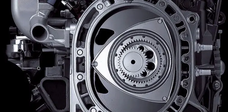
If you look carefully at a rotating motor, you will notice that it consists of several plates assembled like a sandwich. In a traditional rotary engine, that is to say, a 2-rotor (a 13B in our case), we notice the presence of six of these plates. Making the front cover the exception, we will focus on the other five for the time being.
The two larger plates are called rotor housings. As their name suggests, they contain both rotors. The interior of the housing represents the work surface or, if you prefer, the combustion chamber. This surface is in a trochoidal form. In other words, imagine a circle whose ends would have been stretched on a vertical axis to give it an elongated shape. Add two slight inward protuberances at each end of the horizontal axis and you get a trochoidal shape.
If you observe the housing, you will notice that there are two envelopes, one inside and one outside. Between the two, there are dozens of differently shaped passages. The smallest circles on the contour are the holes for the tension bolts. This is what connects the plates. Larger circles represent the oil internal passages. The other openings of various shapes are the conduits for the coolant.

On the inner surface of the housing, it is possible to see two tiny openings. This is the location of the spark plugs. The top one is called the trailing spark plug and the bottom one, the leading spark plug. More on that later. For now, let’s look at the large opening on the side of the housing. It’s the exhaust port of the rotor used to expel the residues of the combustion process. The last element of importance is the passage on the upper left of the housing, used to bring the necessary oil to the apex joints through a slight opening on the inner surface. Unlike conventional four-stroke engines where piston rings are used, it is impossible to lubricate the joints with a surface not exposed to combustion. Indeed, the apex seals act as sealing rings and are exposed at all times. The oil is instead injected directly to lubricate the components, which explains the excessive oil consumption of rotary engines.
The other three plates are called side housing and intermediate side housing. In addition to their sealing role inside the rotor housing, they also contain the engine’s intake ports. The intake ports on the intermediate plate, that is to say, the one at the center of the two rotor housings, are called primary ports. Above these ports are two openings in the intermediate plate for the injectors. It should be noted here that the intake is positioned laterally with the rotor and not facing it as the exhaust ports are. Side plates also contain so-called secondary ports. After 1984, the non-turbo 13B rotary engines have, on their side plates, another pair of apertures for a total of six ports. These two additional ports are named “auxiliaries”. They are opened by high-speed activators to maximize performance and are closed at low speeds to promote torque.
If you look at the illustrations, you will notice that oil is circulating on the surface of these plates. Indeed, when the rotor turns, it creates friction on the lateral surface, which must be lubricated to avoid premature wear of the internal components. It should also be noted that these oil passages limit the size of the intake ports. When tuning a rotary engine, the goal is to find an ingenious way to increase the size of these ports to deliver air and fuel more efficiently to the engine while respecting the engine’s limits.
The most important parts are certainly the rotors and the eccentric driveshaft. If you take a look at the center of the rotors, you can see a jagged surface and a smooth one. This last part represents the bearing of the rotor. The serrated portion is mated with another serrated portion called stationary gears. These are attached to the side plates. The eccentric drive shaft slides through all the elements, from the plates to the rotors and through the stationary gears.
How does a rotary engine work?
The rotors do not rotate on a fixed axis only. Their movement is the sum of two very distinct motions. The first is simple rotation. The rotors achieve this through their bearings (smooth surface) which are constantly in contact with the two lobes of the eccentric shaft. These lobes being offset from the shaft rotation axis, they prevent the rotors from rotating on the same level. The lobes make the rotors orbit around the eccentric shaft’s rotation axis. The final movement is, therefore, a combination of a rotation and an orbit of the rotors.
The cycles of a rotary engine
To better understand the fundamental principle of how rotary engines work, we will use some terms used with traditional four-stroke engines. The TDC (top dead center) is the point where the piston reaches its maximum height, thus minimizing the available space inside the combustion chamber. The BDC (bottom dead center) is the point where the piston is at the lowest point, thus offering the maximum space. We will use the terms TDC and BDC according to the maximum or minimum space that the rotor will provide.
If you start from the TDC, taking the upper left end of the rotor, and turning clockwise, here starts the intake cycle. This ends when the same end reaches the BDC. It should be noted here that the rotor rotates clockwise at one-third of the speed of the eccentric shaft. Between the TDC and the BDC, the eccentric shaft will have turned 270°. That’s 90° more than the 180° required for a four-stroke engine for the same operation.
Again, from the BDC to the TDC, 270 ° is needed to complete the compression cycle. Notice how the air/fuel mixture is compressed against the wall. It’s at this moment that the spark plug lights up to create the combustion. Another 270 ° more and you will reach the BDC ending the combustion cycle. Subsequently, the rotor expels the exhaust gases through the rotor housing exhaust port, traveling the last 270 ° to return to the starting point.
Each of the rotor faces is separated by 120° and simultaneously performs a different cycle than the others. In this way, over 360 °, the three faces of the rotor contribute to ONE power cycle for ONE revolution of the eccentric shaft. On a traditional four-stroke engine, two rotations of 360 ° are required. As a result, a rotary engine has the capabilities of a four-stroke engine twice its displacement. A 13B engine of 1.3L is equivalent to a 2.6L engine. This is where the strength of the rotary motors lies. While being extremely compact, they possess the potential of a much larger engine.
The ignition system on a rotary engine
As mentioned before, there are two spark plugs per plate. The one at the bottom is the leading one and the one at the top is the trailing spark plug. If we take into account that the front rotor housing bears the number 1 and that of the back, the number 2, the name of each spark plugs will be L1, L2, T1, and T2. When the combustion chamber (the convex part on the rotor surface) approaches the TDC during the compression cycle, the leading spark plugs ignite the mixture first. Trailing spark plugs then activate about 10 ° to 15 ° later. It is important to specify that the spark plugs are activated a third time in the cycle. This phenomenon is called “waste spark”. To simplify the ignition system, the spark plugs use the same coil, thus the same signal. Spark plugs L1 and L2 are then activated at the same time. Modern rotary motors use an eccentric shaft position sensor as well as three coils, one for both leading plugs and one for each trailing plug.
The Renesis engine
The Renesis engine of the RX-8 is supposed to be a major improvement in comparison with its older brother, the 13B-REW. The Renesis is also more compact and 30% lighter. The concept of the six intake ports is deja-vu, but the location of the exhaust ports is a real innovation. Compared to previous engines, the Renesis doesn’t have its exhaust ports at the periphery of the rotor housing. It rather uses two ports, one directly on the intermediate plate and the other on the side plate. Engineers say the valve overlap has been reduced, improving fuel efficiency at idle by 40% when compared to the 13B-REW. In short, the Renesis produces fewer emissions, consumes less fuel and the combustion is greatly improved.
Hidden treasures
There are some hidden treasures in the world of rotary engines that few people are even aware of. One such example is the 20B-REW, a biturbo tri-rotor offered in the Eunos Cosmo, a Japanese car that was sold from January 1990 to March 1996. With a displacement of 1962 cm³, the 20B-REW has substantially the same capabilities as a small V8. With a pressure of 10.29 psi coming from the turbos, the power reaches up to 280hp, all probably limited by the restrictions imposed by Japanese laws. To give you an idea, this same engine in atmospheric mode develops 250hp, 320hp if manufactured accordingly. Hard to believe that 10 psi of pressure only produces 50hp more. In truth, with a simple pressure controller, it is possible to easily reach the 400hp mark. With a little more care and devotion, 700hp wouldn’t be impossible to reach at all.

If such power is achievable with a tri-rotor engine, just imagine what would be possible with four! This type of engine is unfortunately not available, except in racing. Among the best known are the 26B which equipped the Mazda 787B, the first Japanese race car to win the 24hr of Le Mans. For those interested, this engine develops nothing less than 700hp at 9000 rpm and 448 lb-ft of torque at 6500 rpm, all in atmospheric mode. The engine having several common parts with the 13B, some say that it is possible to create a custom four-rotor engine using two 13B.
If such an idea sure seems interesting, it’s not hard to imagine how big a budget building a setup would require!